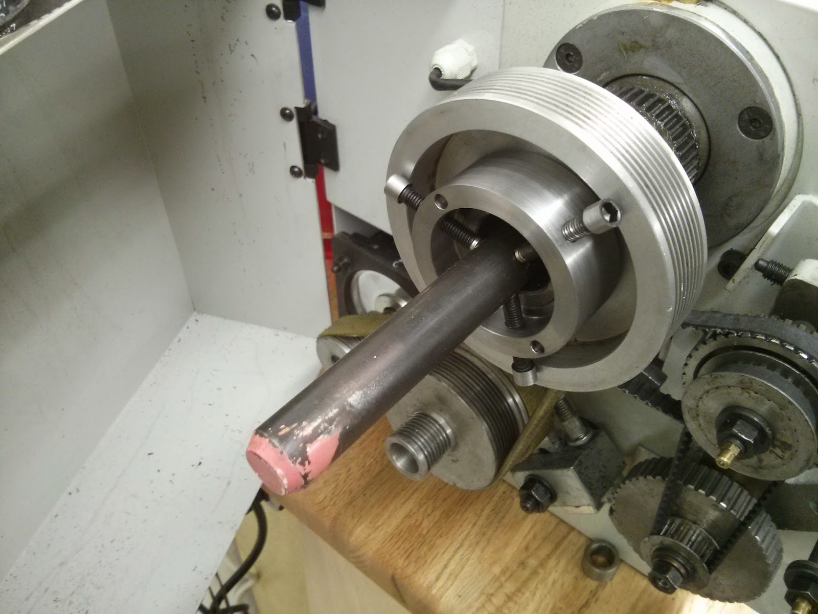
A
spindle spider is used to add another support for long shafts that
extend through the bore of a lathe. Without a spindle spider, the there
is no support left of the chuck and the work piece can flop around
inside of the bore, and this motion may transmit and impact the
machining.
Not all lathes come with spindle spiders. The South Bend SB1001 does
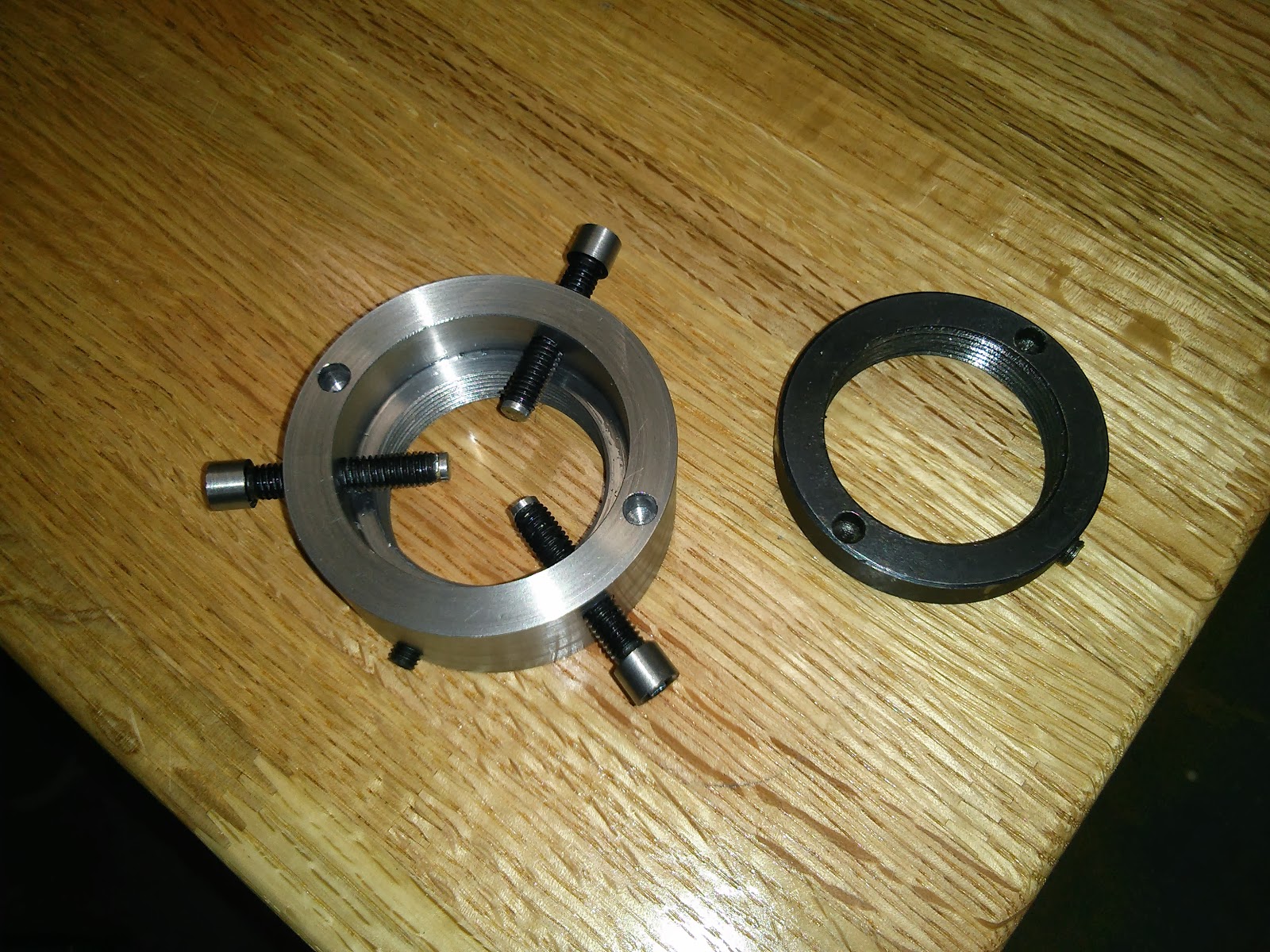
not, but here we will make one. The spindle spider we'll make is shown
to the left of the original SB1001 spindle nut. The stock for the work
piece was 1215 2-1/2" steel rod from McMaster.
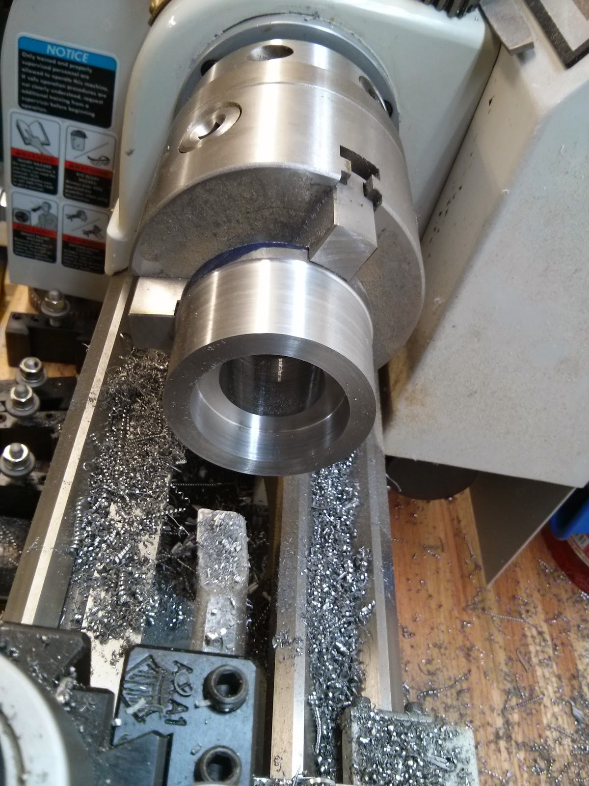
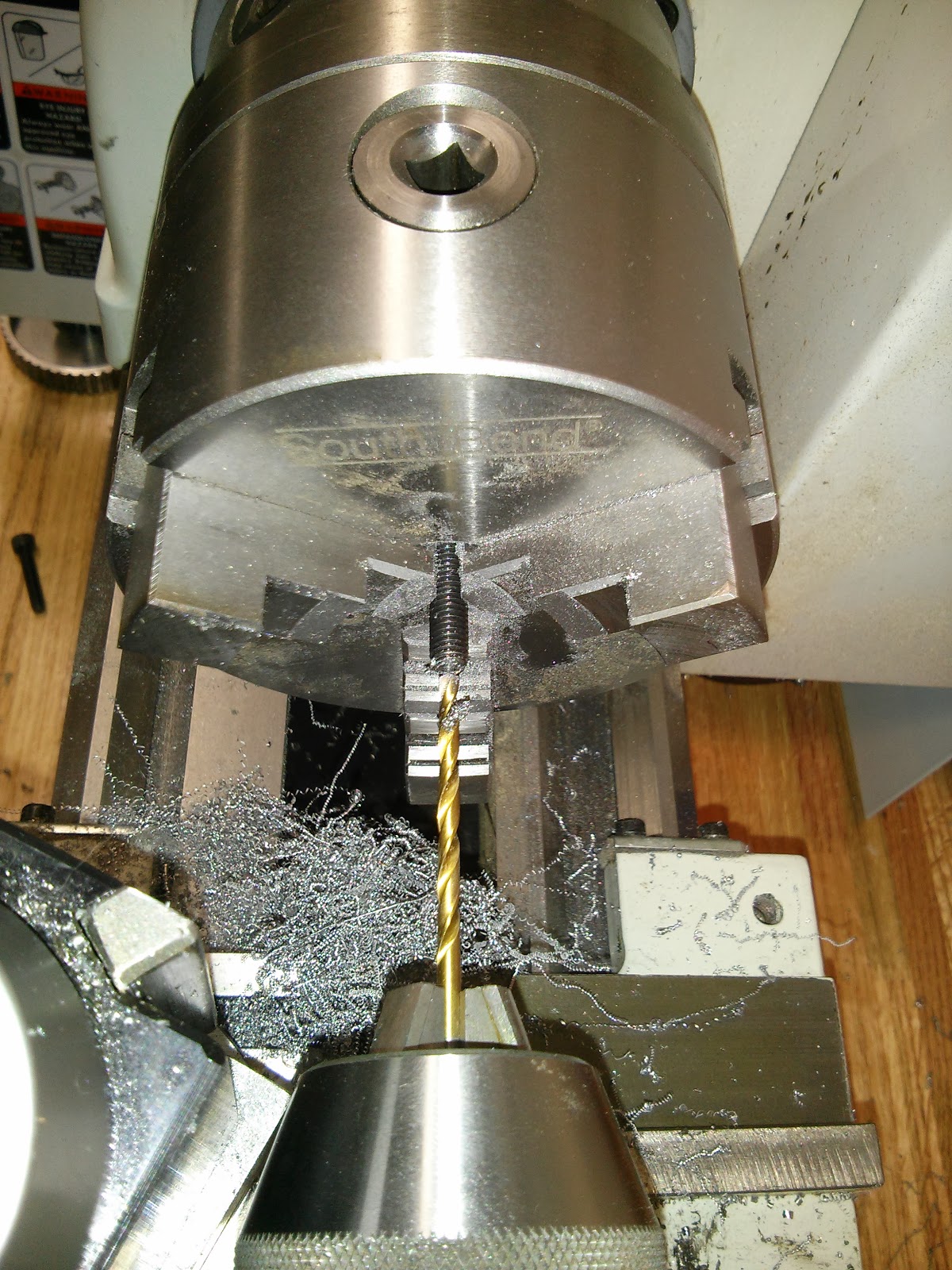
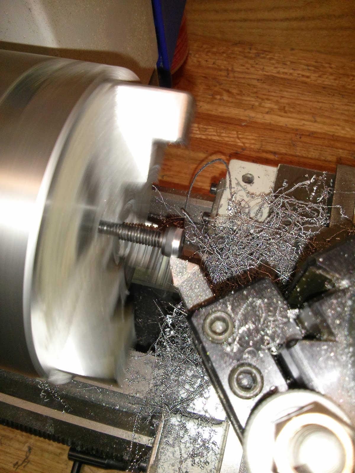
The first operations are to face, turn outside, spot drill, drill 1"
through the center, bore to under minor diameter of the spindle, and
bore thread relief. The outside turning is partially for looks, but
mainly to reduce the diameter so it'll be possible to access a set screw
that locks the spindle spider in place, given it recesses a bit into
the spindle pulley. Spot drill and then immediately drill to a diameter
suitable for boring, e.g. 1". Drill bits are meant to have pressure at
the center of the bit, and step drilling, e.g., starting with 1/4, then
1/2, etc. messes this up, and the chatter can create problems and the
bit can jam.
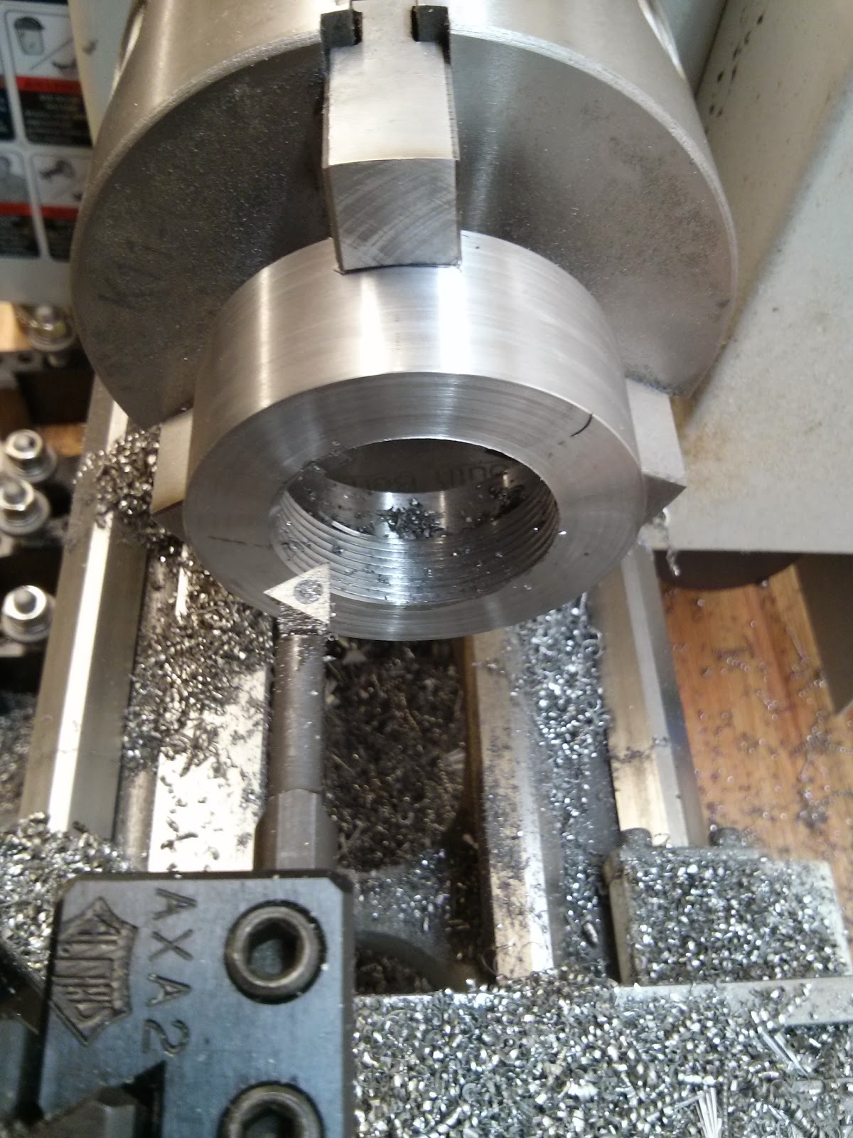
After flipping the work piece over in the chuck the next operations are
remove extra length of material used to previously hold it, bore to
minor diameter, thread 40mm-1.5 thread. After the extra material is
removed, the spindle spider is now to the its final length. Because it's
going to be difficult, especially with a three jaw chuck, to get the
previously bored hole centered with the spindle after flipping the work
piece, finish boring to the minimum diameter after flipping, which also
trues up the bore. To perform the threading, the compound is going to be
rotated around to 60deg, or slightly under, instead of 30deg as would
be used for external threads. Watch a YouTube video on this to make sure
the particular set up is clear. Calculating the depth of cut can be
done with some trig. The SB1001 can't use the thread dial for metric
threads, so at the end of a thread pass, leave the half-nut in place,
advance the cross slide, and put the spindle in reverse to back the
threading tool out of the bore.
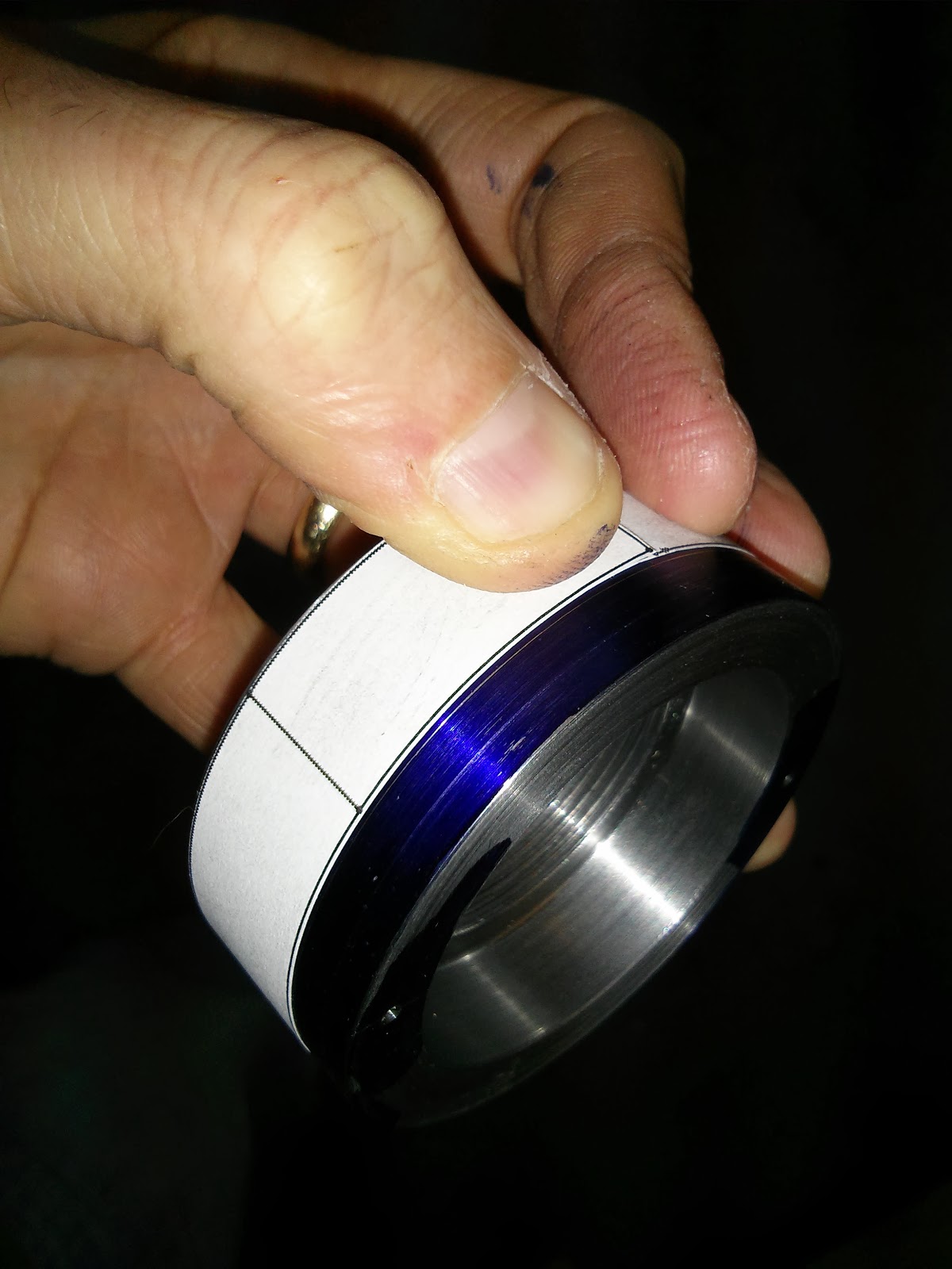
I don't have a rotary table, so to get decent layouts on a
circumference, I create and print a template for layout, e.g., in a CAD
program, hold in place, verify first and last marks line up, whose
distance matches the circumference, and mark positions with a scribing
tool. The layout can aligned against the work piece edge or a line
offset from the edge. If careful, this method seemed to work fine.
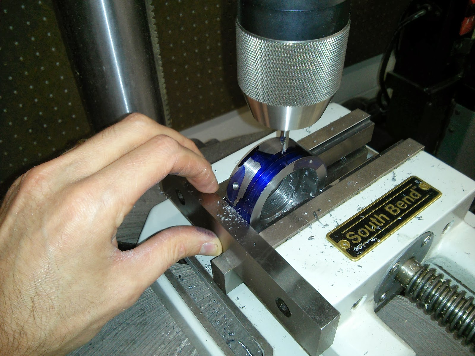
To line up the drill press spindle, a center finder can be used. This center finder can be used to get the correct offset, as well as hit the top, i.e., drill through the center.
Spot drill, drill, tap now or later, rotate, repeat. Use parallels as
additional vice fences to help positioning. As long as the vice is not
moved, it will not necessary to re-indicate work piece center. Line up
spot drill with scribed lines. Drill two shallow holes on outside face
to receive a spanner wrench.
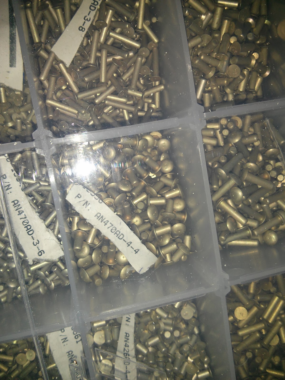
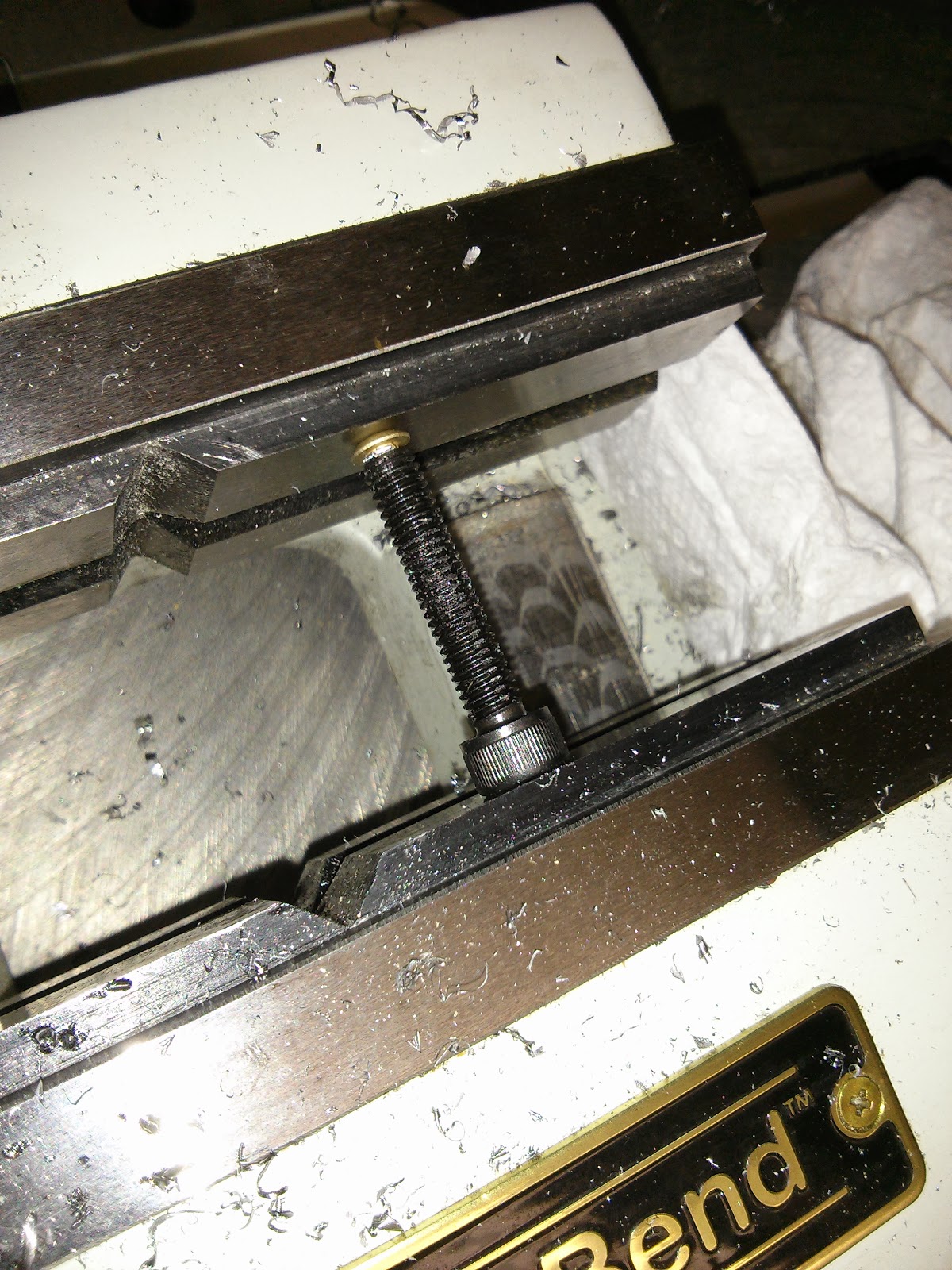
To create non-marring screws for the spider, drill screws to receive
round head aluminum rivets, e.g. AN470AD-4-4. After inserted, turn the
rivet heads down to avoid interference when screwing into nut. The head
of the screw may need to be turned down to avoid interference with the
spindle pulley.
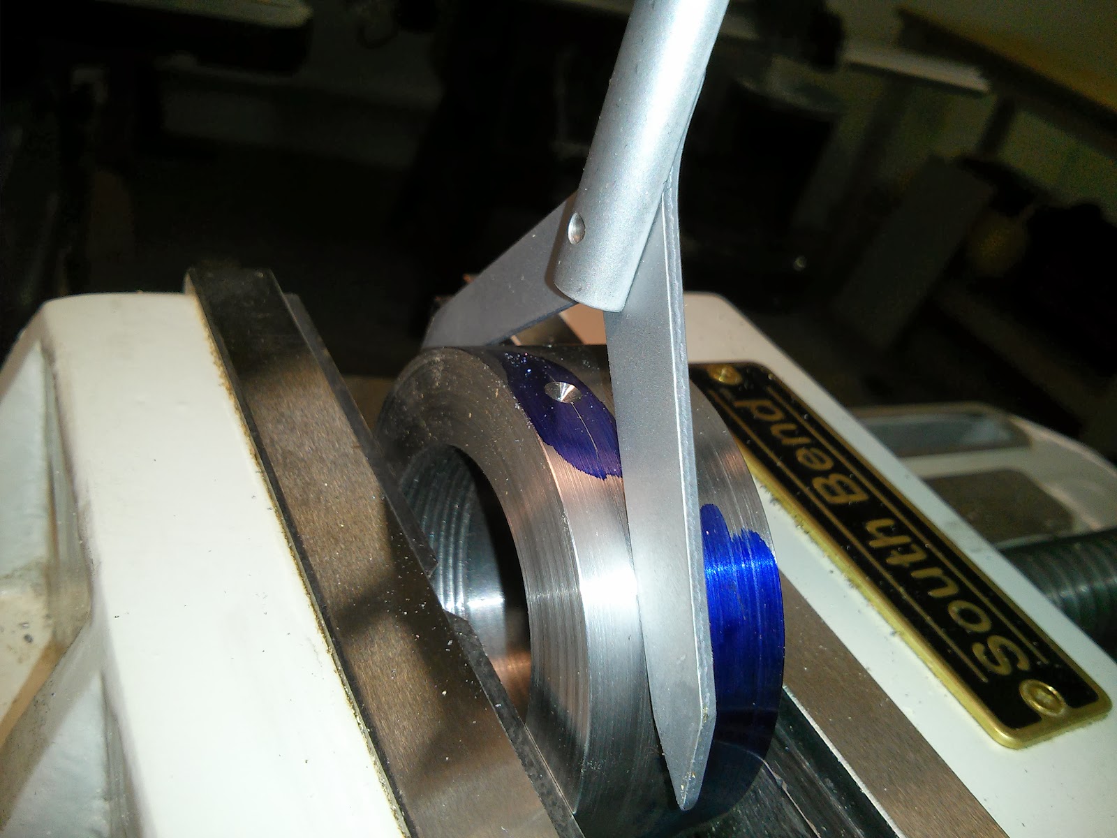
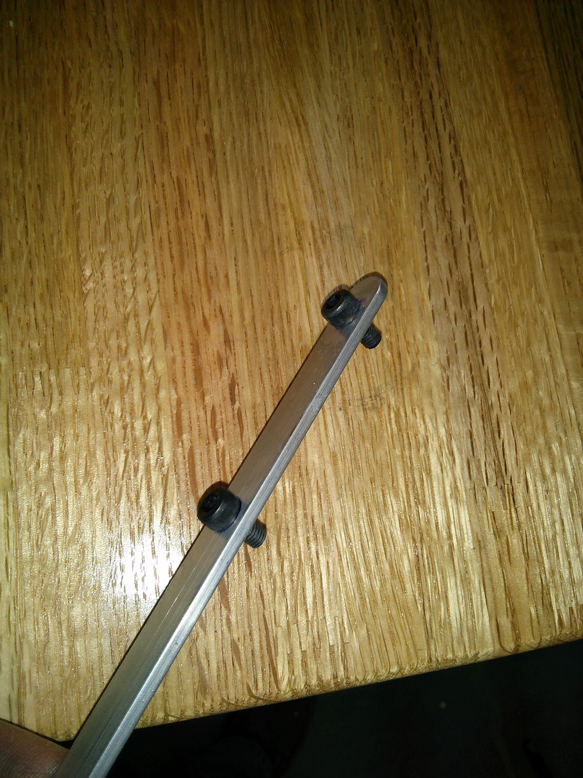
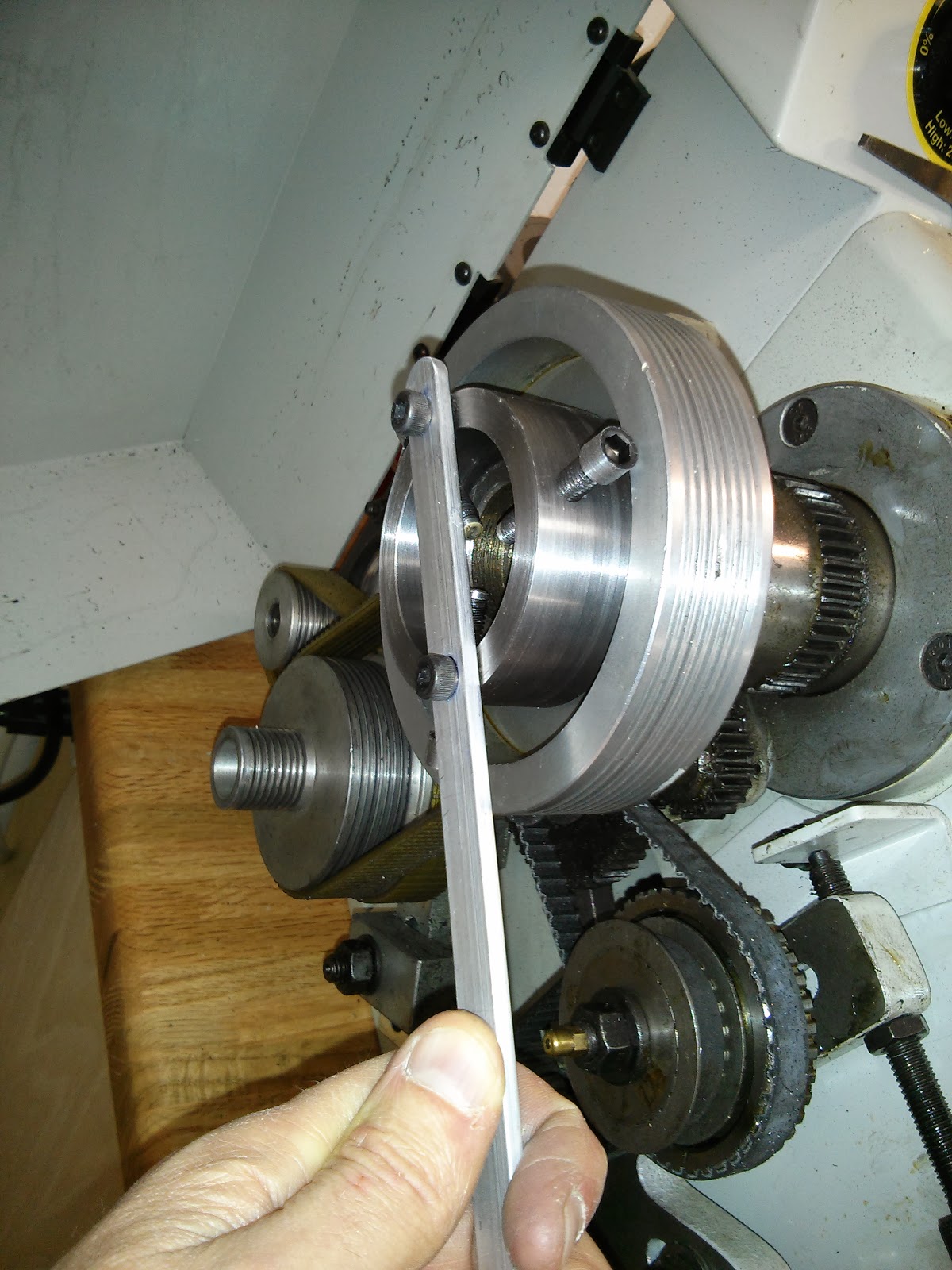
Create a simple spanner wrench using a piece of stock and a couple
screws. Grind the screws to a length that allows the wrench to correct
seat on the spindle spider. Tighten spindle spider onto spindle and
tighten set screw.
Enjoy. Unless the pulley cover is modified, when using the spindle
spider the cover will probably need to be opened. As always, be very
careful to avoid the gears and pulleys when operating the lathe.
