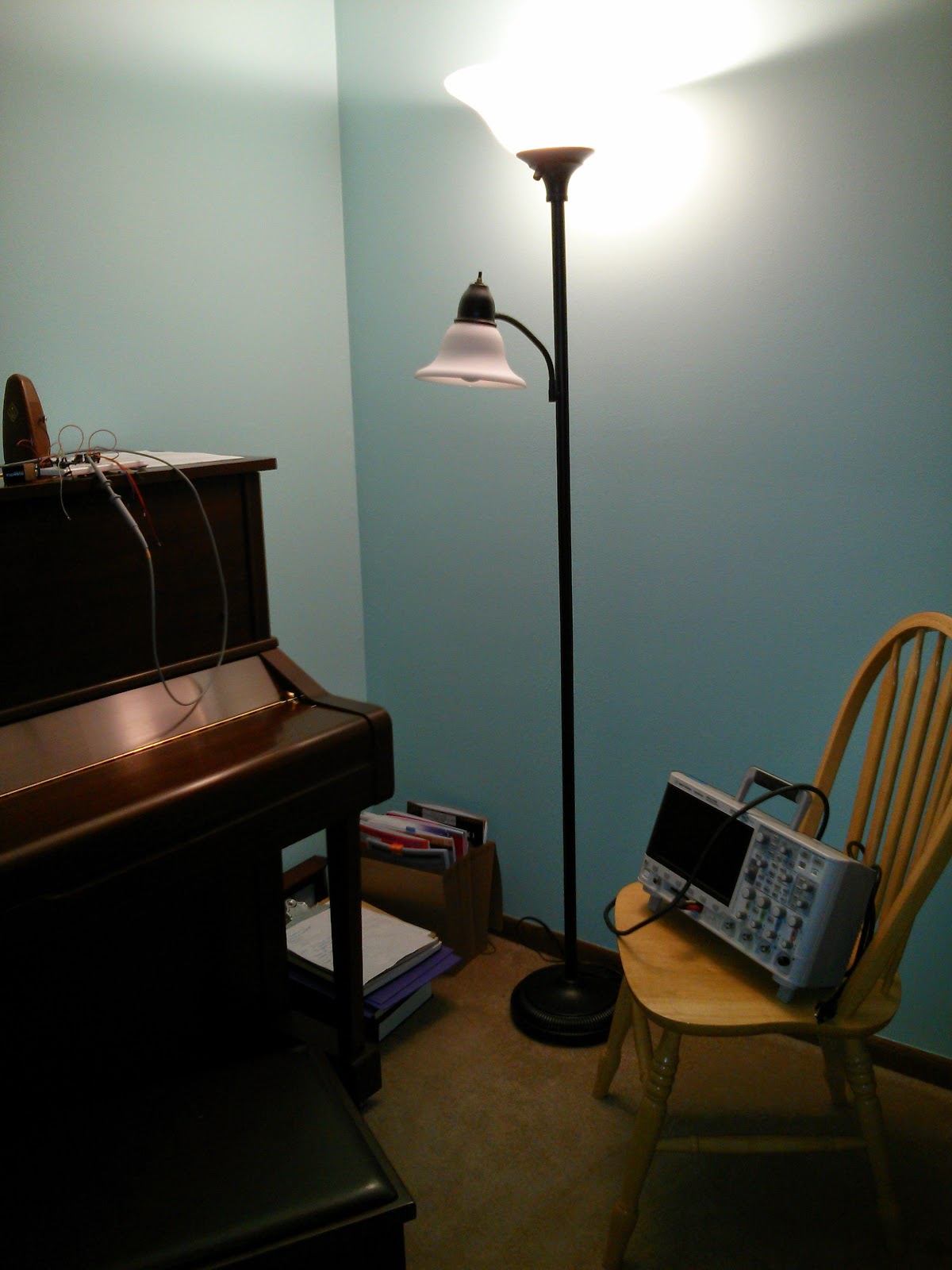
We'll use a voltage divider circuit, with one CdS photoresistor and a standard resistor picked to produce a reasonable voltage divider near the light intensity we'll be measuring. The particular CdS cell I used measured 1 kOhm directly below a 13.5 W LED bulb and 4 kOhm at a typical reading distance, so any resistor near 4 kOhm is fine. After all, we're performing only relative measurements.
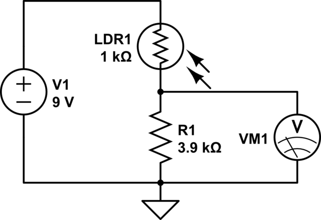
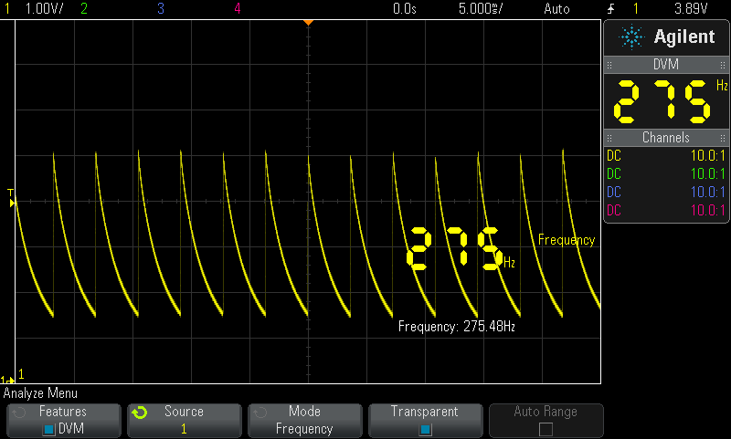
Here we'll use an oscilloscope in place of the voltmeter shown in the circuit. You may be able to use a multimeter with a frequency counter, but without some filtering the frequency counter may be mislead. With the oscilloscope, we can filter several ways including averaging waveforms. To test the circuit, we'll use a stroboscope (Pasco Scientific SF-9211) running at 275 Hz, though anything other than 60 Hz would be fine for verifying we're not simply picking up line noise. Several other other lower frequencies were tried and the measurements agreed well with the stroboscope. With this simple circuit and an oscilloscope we can see the characteristic flicker of the particular light source even if imperceptible.
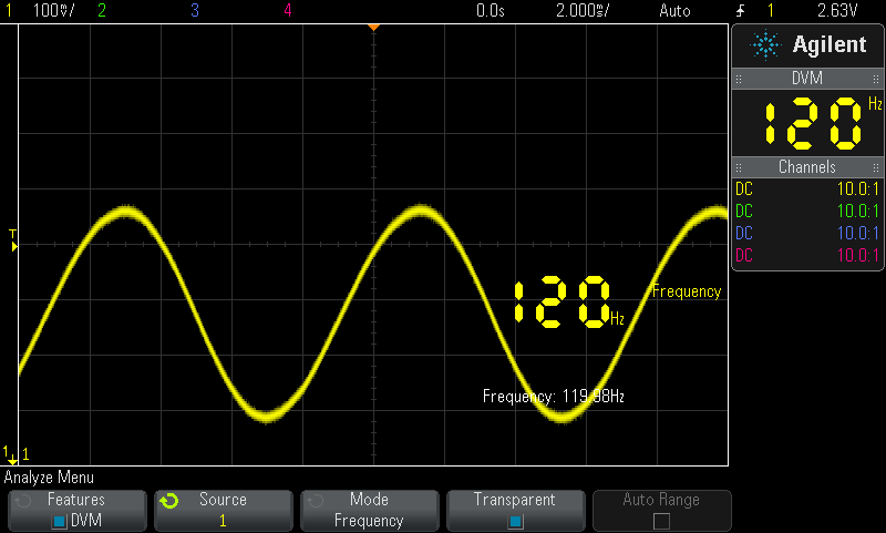
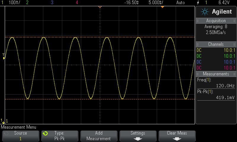
Now, we'll check a standard desk lamp. The measured waveform is sinusoidal, but the 120 Hz frequency may be unexpected. Recall the AC waveform will have two peaks and two zero crossings each cycle. So, the light will flicker at a frequency twice that of the AC source. With more light falling on the photoresistor, the measured voltage will be greater than with less light. Peaks in the measured waveform correspond to light output peaks. Valleys in the measured waveform correspond to low spots in the light output, when the AC voltage to the light crosses 0 VAC. There will be some lag between changes in the light and measurement due to response rate of the photoresistor but for the frequencies are are examining the lag should have minimal impact.
Moving to our torchiere, first measure it at full brightness
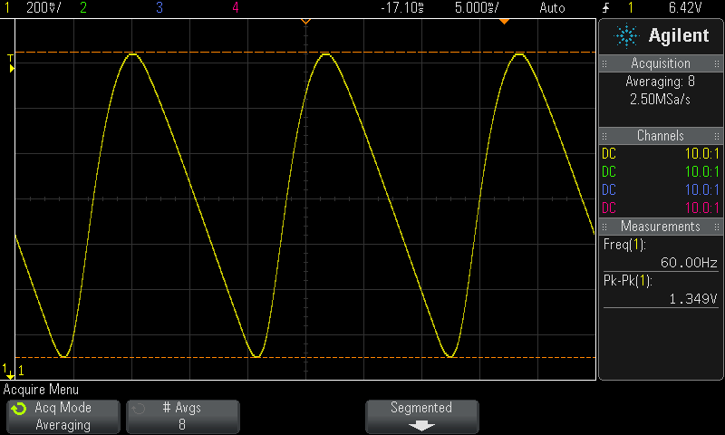
then at half brightness, where we see the light's flicker has halved so the AC frequency has halved. While efficient, it's a pretty crummy way to reduce the brightness when the induced flicker is considered. The waveform is no longer sinusoidal when the light is run at 50% intensity. (I'll open the light up soon to see what circuit is actually used, but it'll be simple.)
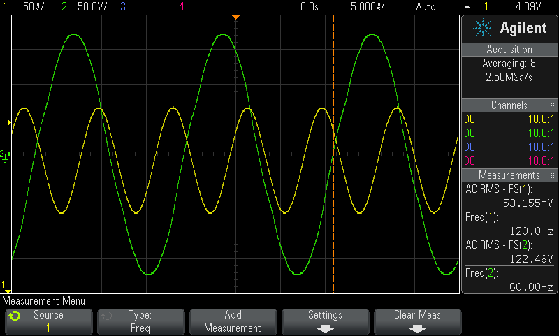
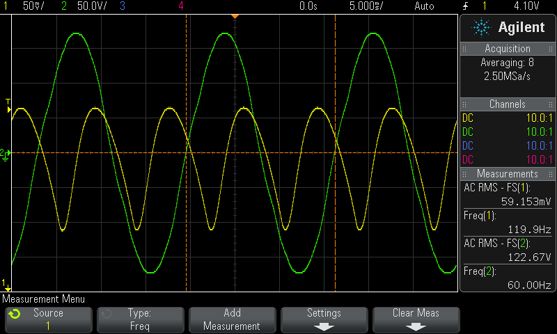
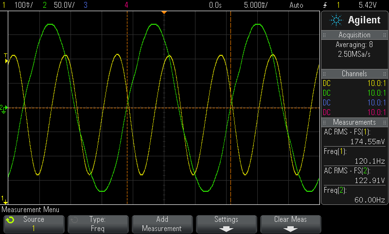
Curious about the flicker being more perceivable with an LED than incandescent bulb, and the different waveform when running the torchiere at 50% power, other bulbs were tested in a standard desktop lamp. The same measurement setup was used, but the line current was also measured. (For safety, do not repeat this. It's too easy to get hurt or burn out your oscilloscope.) Other than the different vertical scale for the brighter LED bulb, the graphs are easy to compare.
A few observations follow. The fluorescent light's deviation from a perfect sinus wave suggests its light decays slower than it brightens. The graphs of the incandescent and LED lights are clean sinusoidal waves. The LED light has a faster response rate than either the fluorescent or incandescent, this is shown by the slope of the LED curve during the approximate linear phase being steeper. While the incandescent continues to glow due to retained heat and the fluorescent continues to glow due to the phosphors, the LED can switch more quickly. What observations can you make of the graphs?
60 W Sylvania incandescent
13 W Conserv-Energy CFL
13.5 W Cree LED
Andy Gock wrote a similar article comparing camera flash duration using a phototransistor instead of a photoresistor.